HOW TO CHANGE THE ACCELERATION OF YOUR CASTER DRIVE SYSTEM

Improve Your New System
Congratulations, you have purchased a caster drive system and have been enjoying learning how the new drive system can benefit your work environment. After familiarizing yourself, you realize that changing the acceleration might improve your new system. Maybe you are carrying a different load than expected, your work environment has more traction than others, or maybe it’s something else.
Whatever your reason, thankfully, this is a straightforward process requiring minimal equipment to make this change.
So, Let’s Get Started
First, let’s go over the equipment needed. Your caster drive system consists of a Roboteq motor controller. A USB Connector of type B, shown in Figure 1, is needed to connect the motor controller to your computer.
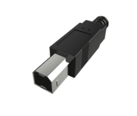
Figure 1. USB Connector Type B
Your Roboteq motor controller also needs the Roborun+ software to be downloaded to change its acceleration settings, as shown in Figure 2. You can download this software from the following link:
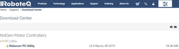
Figure 2. Roborun+ Software File
Now that you have downloaded and gathered all the necessary software and equipment, we can discuss the process for changing the acceleration of the drives.
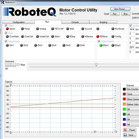
Step 1: After successfully downloading the Roborun+ software, let’s start by opening it. Figure 3 shows the opening page of Roborun+.
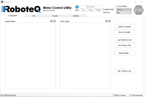
Figure 3. Roborun+
Step 2: Locate your DRIVE CASTER® system’s USB port and connect the motor controller to your computer using the USB type B cable below in Figure 4.
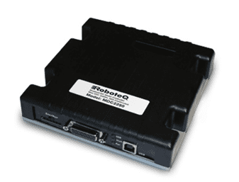
Figure 4. Roboteq’s USB Port
Step 3: Power your drive system by turning it on. Then, once the motor controller is found, Roborun+ will prompt you to read the controller configuration and select ’Yes,’ displayed in Figure 5.
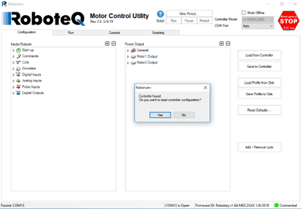
Figure 5. Controller Found
Step 4: Go to the ‘Power Output’ section under the configuration tab. Expand the ‘Motor 1 Output’ tab, shown below in Figure 6.
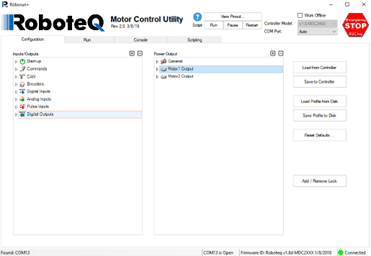
Figure 6. Motor 1 Output Tab
Step 5: Go to the Motor 1 Output tab. Locate and expand the ‘Speed & Acceleration’ tab shown in Figure 7.
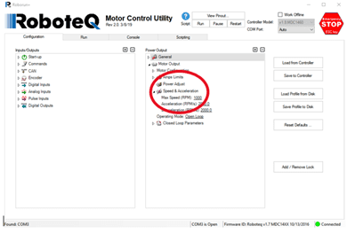
Figure 7. Speed & Acceleration Tab
Step 6: Make the needed changes to the acceleration and deceleration. Adjust the ‘Acceleration (RPM/s)’ and ‘Deceleration (RPM/s)’ settings as needed, shown in Figure 8. Changing these values will adjust the revolutions per minute per second, thus changing the time needed to reach the maximum speed and the time needed to come to a complete stop. Adjusting the ‘Max Speed (RMP)’ setting will not change the motor speed while operating in the ‘Open Loop’ mode.
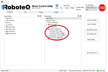
Figure 8. Motor 1 Acceleration
Step 7: Go to Motor 2 of your drive system. Locate and expand the ‘Motor 2 Output’ tab in Figure 9. Make the necessary changes as you did above with Motor 1.
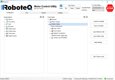
Figure 9. Motor 2 Acceleration
Step 8: Save your changes. Once adjustments have been made, select the ‘Save to Controller’ button on the right of the screen, shown in Figure 10.
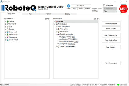
Figure 10. Save Changes
Finishing the process
You can now unplug the USB cable and test your drive system’s new acceleration and deceleration settings. Check out our other drive system tutorials if you have any additional questions. As always, feel free to contact the Conceptual Innovation support team.